
Control Actuator Design Principles – Task Evaluation and Information Collection
The selection of control actuators appropriate for workers tasks involves an iterative procedure as follows:
- Task evaluation and information collection (this section)
- Intermediate selection of control families (see next section)
- Identification of suitable control types (see section after next section)
General requirements
The initial step of the task evaluation and information collection is to define the general task requirements. The task of the operator is evaluated referring to the accuracy required in positioning the control actuator:
The accuracy is determined by the task that is asked to be performed and is influenced by several factors. The most important is continuity of movement required. A discrete control actuator movement is one where the control actuator can only be moved to a limited number of fixed positions. The error in selecting the correct position increases with the number of discrete positions. Accuracy can be improved by, for example, clear information on the current value of the controlled variable, by clear labelling or by placing the actuator where it can be easily seen and moved.
Where movement of a control actuator corresponds to a continuous change in a controlled variable, the extent to which it deviates from the required value is a measure of error. The probability of making an error depends mainly on
- the time allowed to complete the task (i.e., speed),
- availability of feedback of information to the operator and
- operating force.
The task of the operator is evaluated referring to the speed of setting required.
The speed is related to the time to complete a control actuator movement. This includes the time to reach and grasp the actuator and time to make the control movement. High speed of operation is inconsistent with a high force requirement. Thus, for continuous tasks, such as keyboard operation, where high speed is necessary the operating force should be kept low.
The task of the operator is evaluated referring to the availability of feedback of information to the operator.
Sensation and feedback keep us in touch with our environment. Ergonomic feedback design is important to allow the worker to perform his/her task, i.e., it allows the worker to decide whether systems task goals have been achieved and whether adjustments are required. Control actuator design is feedback design in that
- the arrangement should help to quickly identify and interpret the operational situation,
- the arrangement shall allow the worker to identify the design and functional structures of the respective machine,
- the assignment shall reflect the process, causes and/or consequences of the operating situations of the respective machine.
Feedback quality will improve when control actuators are recognised and distinguished. This can be achieved by coding as an information interface design principle, applying labels, symbols, shape, size, position, distance, and colour coding (e.g., dual coding of traffic light). Control actuator design should match operator information acquisition and perception (see Table 1).
|
Information acquisition and perception |
Example of design parameters |
| visual | quick visual detection and recognition of a switch position, decoding red colour of an emergency stop switch |
| tactile | noticeable feeling of a switch position. Overcoming the initial resistance1 of a control unit |
| haptic | touch detection of surface properties of a control unit (size, contour, compliance, temperature) |
| proprioceptive2 | variable setting resistance over the movement path of the control unit (setting characteristic) |
| acoustic | perceived audible "click" when a switch clicks into place |
1 Initial resistance is the resistance whose overcoming makes the actuation possible in the first place (avoidance of disturbance variables, muscle tremor, etc.). 2 Proprioceptive information feedback takes place directly by transmitting muscle tension and stretching to the brain during movement (on certain nerve tracts). |
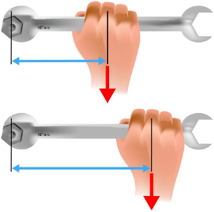
The task of the operator is evaluated referring to the force/torque requirements.
Control actuators may be used to move parts of a machine (see Figure 1) and for these movements may be needed large forces/torques. In these cases, machine design should allow mechanical or power assistance to minimize the load on the operator when using the control actuator.
Specific requirements
The second step of the task evaluation and information collection is to define the specific task requirements. The task of the operator is evaluated referring to the visual check of control actuator setting.
Using control actuators, it is important to give feedback to the operator that the correct control action has been performed (e.g., changing the reading of a display, a visual or audible changing in the process).
The task of the operator is evaluated referring to the tactile check of setting.
The operator's vision can be fully occupied, or the control actuator is located away from the operator's field of vision. In these cases, it is important the actuators to be readily identified by touch.
The task of the operator is evaluated referring to inadvertent operation avoidance.
Where very high risks are present the following measures should be considered:
- use two hand controls,
- use a lock-out system,
- locate control actuator in a recess,
- shroud the control actuator.
The task of the operator is evaluated referring to the friction to avoid hand slipping from control actuator.
Where manual control actuators are used continuously or frequently, it is important to ensure that the operator's hand does not slip on the control actuator's surface. This will be particularly important where a requirement for high force application has been identified or when there is the continuously use of gloves.
The task of the operator is evaluated referring to the ease of cleaning.
It is important to ensure that control actuators are easy to clean.
Movement characteristics
The third step of the task evaluation and information collection is to define the movement characteristics. The task of the operator is evaluated referring to:
- Type of movement: linear or rotary.
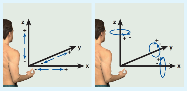
- Axis of movement (see Figure 2).
- Direction of movement: the direction to actuate the control relative to the axis as shown in Figure 2 "+" and "-" directions are indicated for both linear and rotary movements.
- Continuity of movement: continuous or discrete.
- Angle of rotation for continuous rotary movements: ≤ 180° or ˃ 180°.
The characteristics of the various types of control actuator need to be considered to determine the available selection options.
References
- EN 842:1996+A1:2008 - Safety of machinery. Visual danger signals. General requirements, design and testing. Brussels: CEN.
- EN 894-1:1997+A1:2008 - Safety of machinery - Ergonomics requirements for the design of displays and control actuators - General principles for human interactions with displays and control actuators. Brussels: CEN.
- EN 894-2:1997+A1:2008- Safety of machinery - Ergonomics requirements for the design of displays and control actuators - Displays. Brussels: CEN.
- EN 894-3:2000+A1:2008 - Safety of machinery - Ergonomics requirements for the design of displays and control actuators - Control actuators. Brussels: CEN.
- EN 981:1996+A1:2008 - Safety of machinery - System of auditory and visual danger and information signals. Brussels: CEN.