
Control Actuator Design Principles – Intermediate Selection of Control Families
The selection of control actuators appropriate for workers tasks involves an iterative procedure as follows:
- Task evaluation and information collection (see previous section)
- Intermediate selection of control families (this section)
- Identification of suitable control types (see next section)
Intermediate selection of control families matches general task requirement and movement characteristics to select suitable control families referring to grip characteristics.
A preselection of control families is the next step in the selection among existing or the design of new control actuators. EN 894-3 presents more requirements and informs in detailed about the procedure.
Information required for the present step is as follows:
- detailed description of tasks requiring use of control actuators and
- assessments from previous chapter on “Task Evaluation and Information Collection”.
The detailed description of the task should contain:
- The person involved (e.g., the worker operating the machine),
- the machine or device addressed (e.g., kneading machine) and
- an interaction activity of the worker (e.g., detect exemptional machine activity and emergency stop the machine).
- Workers tasks, each in one short sentence (e.g., worker emergency stops machine).
Assessment according to task evaluation and information collection (see previous section):
- Decide on degree of requirement for accuracy as well as speed and force for the requested activity of the worker.
- Choose among movement characteristics referring to axis and direction of rotation as well as of temporal characteristics (discreet vs. continuous movement).
Hand grip characteristics
The task of the operator is evaluated referring to:
- Part of body applying force: foot, hand, finger, or other body parts.
- Type of grip: contact, pinch, or clench.
- Method of applying force: normal or tangential.
- Type of foot contact: total foot, forefoot, heel.
When control actuators are actuated, a certain minimum resistance (initial resistance) must be maintained to be perceptible.
It ensures the feedback feeling necessary for perception at the beginning of the switching or operating process. It can also help to prevent unintentional actuation.
For fine tasks, the initial resistance may be less than 0.5 N (see EN 894-3). If the initial resistance is too high, however, repeated actuation leads to excessive fatigue.
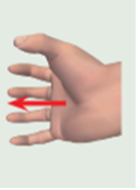
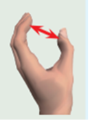
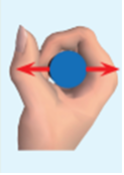
Examples of grip characteristics of manual control actuators are show in Table 1.
| Example | Type of grip | Part of hand applying force | Method of applying force |
|---|---|---|---|
|
Contact actuation | Hand | Normal |
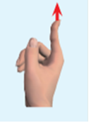 |
Contact actuation | Finger | Normal |
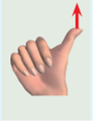 |
Contact actuation | Thumb | Normal |
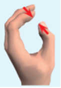 |
Pinch actuation | Finger | Tangential |
 |
Pinch actuation | Hand | Tangential |
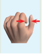 |
Pinch actuation | Thumb opposed | Normal |
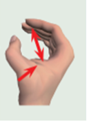 |
Clench actuation | Finger | Tangential |
 |
Clench actuation | Hand | Normal |
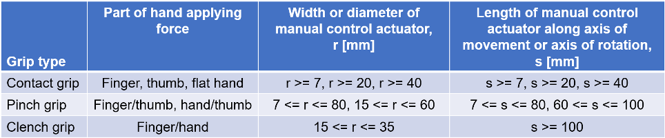
Once grip characteristics are selected, corresponding dimensions should be identified (see Table 2).
Table 2: Minimum dimensions relevant for selection of grip characteristics of control actuators (see EN 894-3, 33).
Regarding gripping handles, dimensions as shown in Table 3 are recommended.
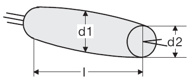 |
Lenght l in mm | diameter d1 in mm | diameter d2 in mm |
| minimal | 90 | 28 | 18 |
| average | 100 | 32 | 22 |
| maximal | 120 | 38 | 28 |
Minimum distances from edges, corners and protruding parts must not be exceeded. These distances result from the space required for the approach of the hand and the space required for the fingers when actuating (see Figure 1).
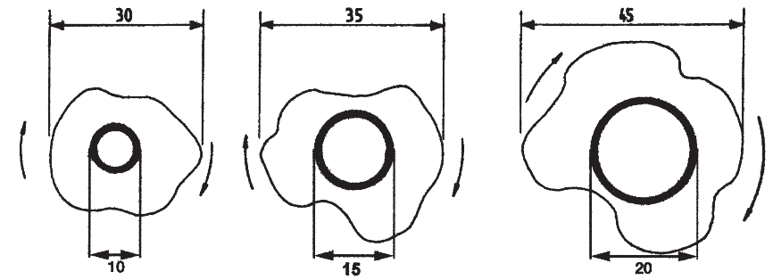
Regarding the shape of the control actuator as presented in Table 2, dimensions as in Table 3 are of relevance.
Shape of the control actuators and handles are important criteria for selection. Handles that deviate from the simple cylinder shape are preferable (see Figure 2). Spherical grips, possibly with finger bulges corresponding to the palm rest and hand posture, are to be preferred.
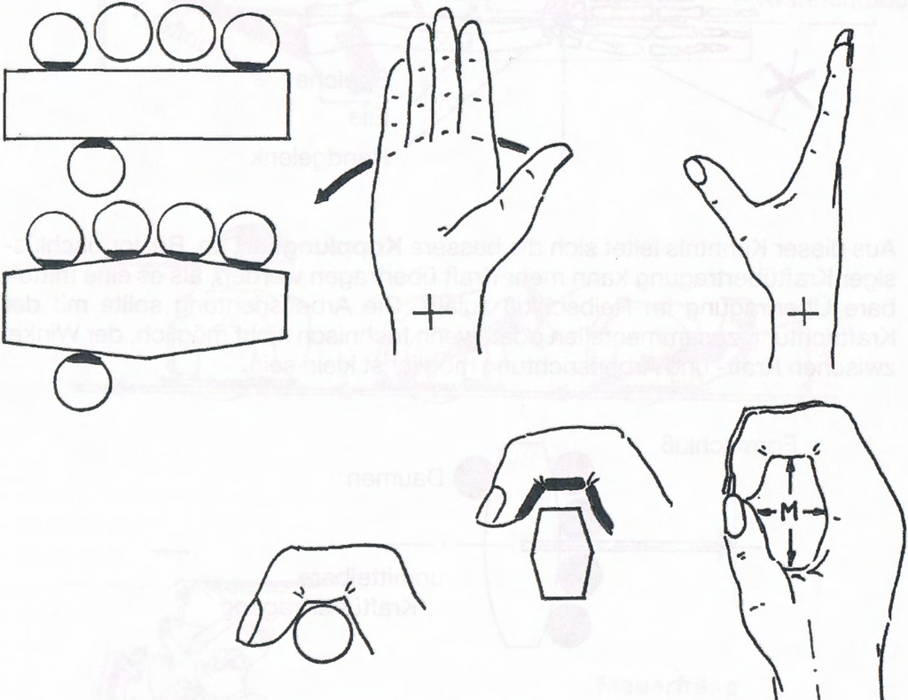
The hand should wrap and surround the handle with the largest possible palm and finger area, as shown by this grip shape.
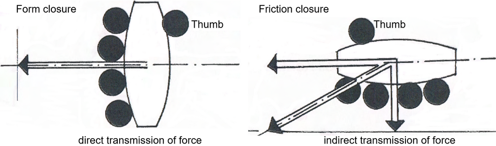
The type of coupling (direct or indirect force transmission) must also be taken into account. With indirect force transmission, the force acts on the contact surface (frictional closure), for direct force transmission in a plane that is perpendicular to it (form closure) (see Figure 3). If high forces have to be transmitted direct force transmission shall be used.
Foot contact characteristics
The task of the operator is evaluated referring to:
- Part of body applying force: foot, hand, finger, or other body parts.
- Type of grip: contact, pinch, or clench.
- Method of applying force: normal or tangential.
- Type of foot contact: total foot, forefoot, heel.
Examples of foot contact characteristics of manual control actuators are show in Table 4.
| Type | Sketch |
| total foot support | 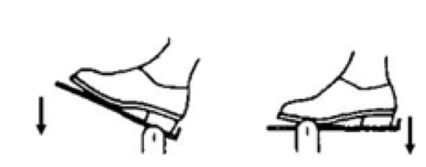 |
| forefoot support | 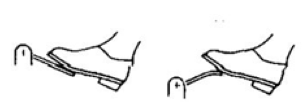 |
| forefoot or heel support | 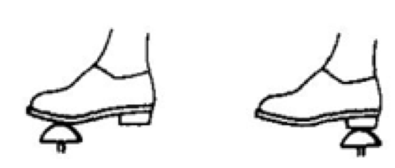 |
With a necessary increase of the actuating force, the type of gripping usually changes from the contact grip to the wrap-around (clench) grip or to the pedal type.
Advantages of pedal and leg operated units:
- The hands of the worker are free for other activities.
- The actuation time is shorter, since as a rule the control unit contact does not have to be released.
- No obstruction by controls in the movement area of hands and arms.
- Possibility of large power transmission with leg actuation.
- No harmful skin contacts possible.
Disadvantages of pedal and leg operated units:
- Intense static muscle work occurs when the body is standing upright.
- No high positioning accuracy.
- Position can be badly perceived.
- As a rule, only one actuator can be used for one foot.
- The application area is restricted.
Consider that controls can be operated with one or both hands and feet. Handedness and footedness should be taken into account.
References
-
EN 894-3:2000+A1:2008 - Safety of machinery - Ergonomics requirements for the design of displays and control actuators - Control actuators. Brussels: CEN.